2019-03-28
For the last eight years or so, I've been carrying around an Arduino (not literally on my person, but, you know, amongst my treasures), waiting for just the right time to start tinkering with it.
That time, it turns out, was yesterday afternoon. This post outlines some of things I've learned so far.
Ard-what-now?
An Arduino is a microcontroller board. The board contains a CPU (central processing unit) along with some I/O (input / output) connections. You can think about it as a small circuit - a circuit that happens to contain a programmable computer on a chip. A chip that you can learn to easily program.
Here's a picture of my Arduino (of the Uno varietal):
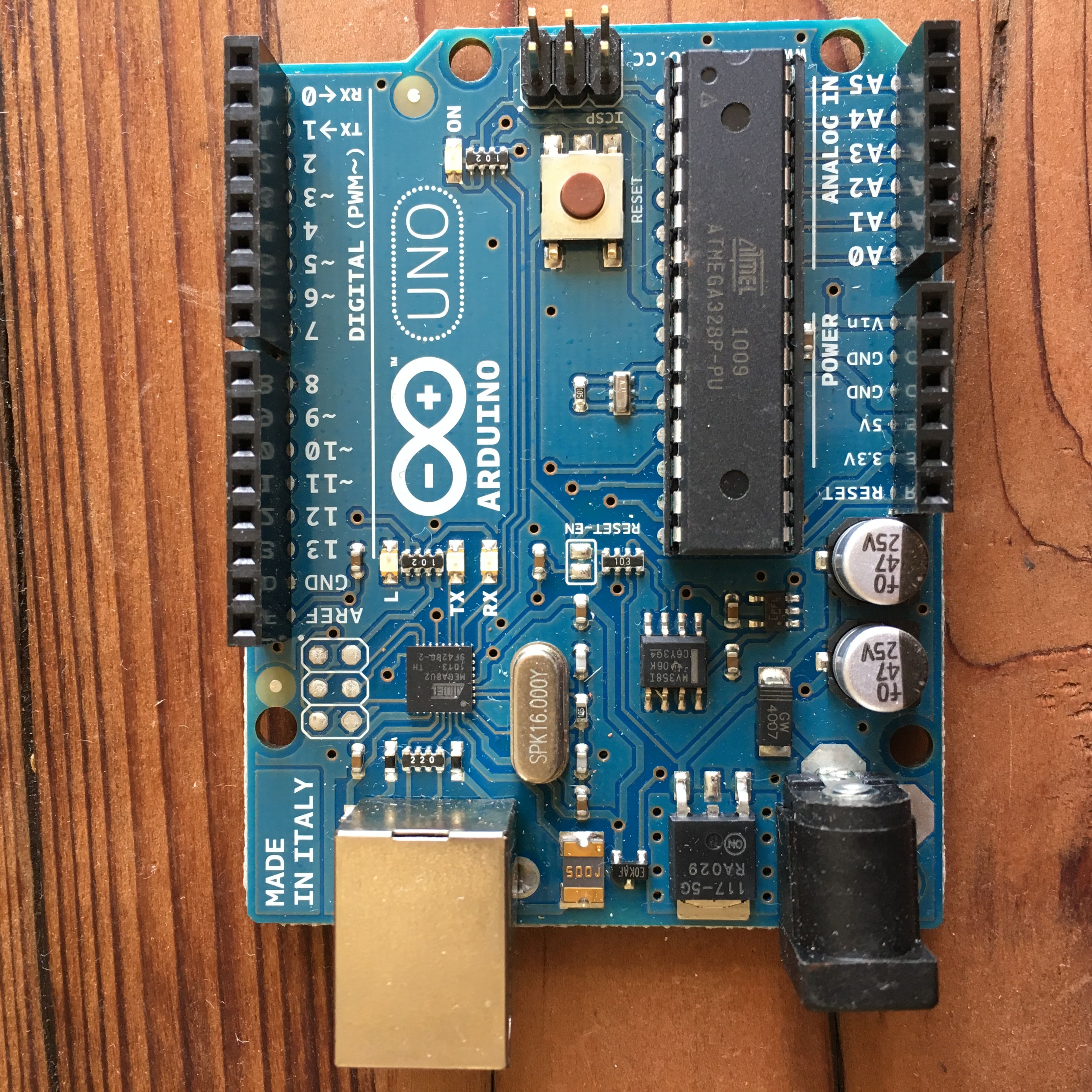
I love the MADE IN ITALY mark in the upper left.
The microprocessor (the computer chip) is the long flat black rectangle near the bottom-right corner of the device. It has 28 pins (14 on each side). Along the top edge of the Arduino you can see a strip of black input pins - these are the Arduino's "digital" pins (meaning that they can either be "on" or "off"). Below the CPU on the bottom right you can see another 5 "analog" pins (meaning that they can receive analog / continuous signals), and then a few "power" pins to the left to provide voltage, ground, and some other stuff that I don't know about yet.
Arduino vs Raspberry Pi
At this point, you might be asking yourself, "How is an Arduino different from a Raspberry Pi?"
It's a good question, since both are affordable, adorable, tiny little computers that you can buy for about $30 bucks or less. But the Raspberry Pi is a full-on Linux computer. An Arduino is... not. Instead, the Arduino computer holds just one program at a time. It stores this program in durable memory, so that you can turn the Arduino on and off, and it will still "remember" its latest program. It's more like a single-purpose device -- except you can dream up and build that single-purpose as many times as you want.
Open-source roots
The company behind Arduino is a non-profit and the Arduino itself is open-source - which means that anyone can build an Arduino board themselves. The original idea behind Arduino was to make a simple device that designers and artists could use for rapid prototyping of physical computing projects that use sensors (aka inputs like a keyboard or mouse or motion detectors) and actuators (aka outputs like a display or printer or lights) to interact and communicate with us human beans. Cool.
Arduino is closely tied to the Processing community. In fact, that's a bit of an understatement, since you actually write Processing code when writing programs for the Arduino -- and, just like in Processing, these programs are also called Sketches. I was happy to see this, since one of my earliest computing classes was Jer Thorp's Introduction to Processing course (which I unabashedly recommend, by the way).
As I mentioned, anyone can download the open-source schematics for Arduino and build a board themeselves with basic components. But if you'd like to make your tinkering lifestyle easier, then I suggest picking up a pre-assembled Arduino from a retailer like Makershed or Adafruit. The kit I bought (eight years ago) is the MAKE: Getting Started With Arduino Kit -- the current version (v3) appears to be retailing for $79.99 bucks. IMHO, it's definitely worth it -- the kit comes along with a bunch of goodies that help you get started right away, like a breadboard, colorful wires, clickable switches, LEDs, sensors, and a friendly introductory book. I also picked up Arduino: A Quick-Start Guide by Maik Schmidt, and I've been enjoying this book as well.
Fun with LEDs
I believe you're legally required to write a program that blinks an LED on and off as your first project with Arduino.
If you asked me a few days ago about LEDs - yeah, sure, I know about LEDs. Those little red lights in things like my Game Boy. Stands for... light emitting... diode.
Great, you continue, what's a diode?
Um.
This is already one of the fun things about playing with Arduino. There are all sorts of basic electronics stuff that I sorta know about, but couldn't explain to a five-year-old or to a rubber duck on my desk. Or just don't know at all. But Arduino is helped me tackle these topics in a practical, tangible way.
So, let's take a look at an LED together.
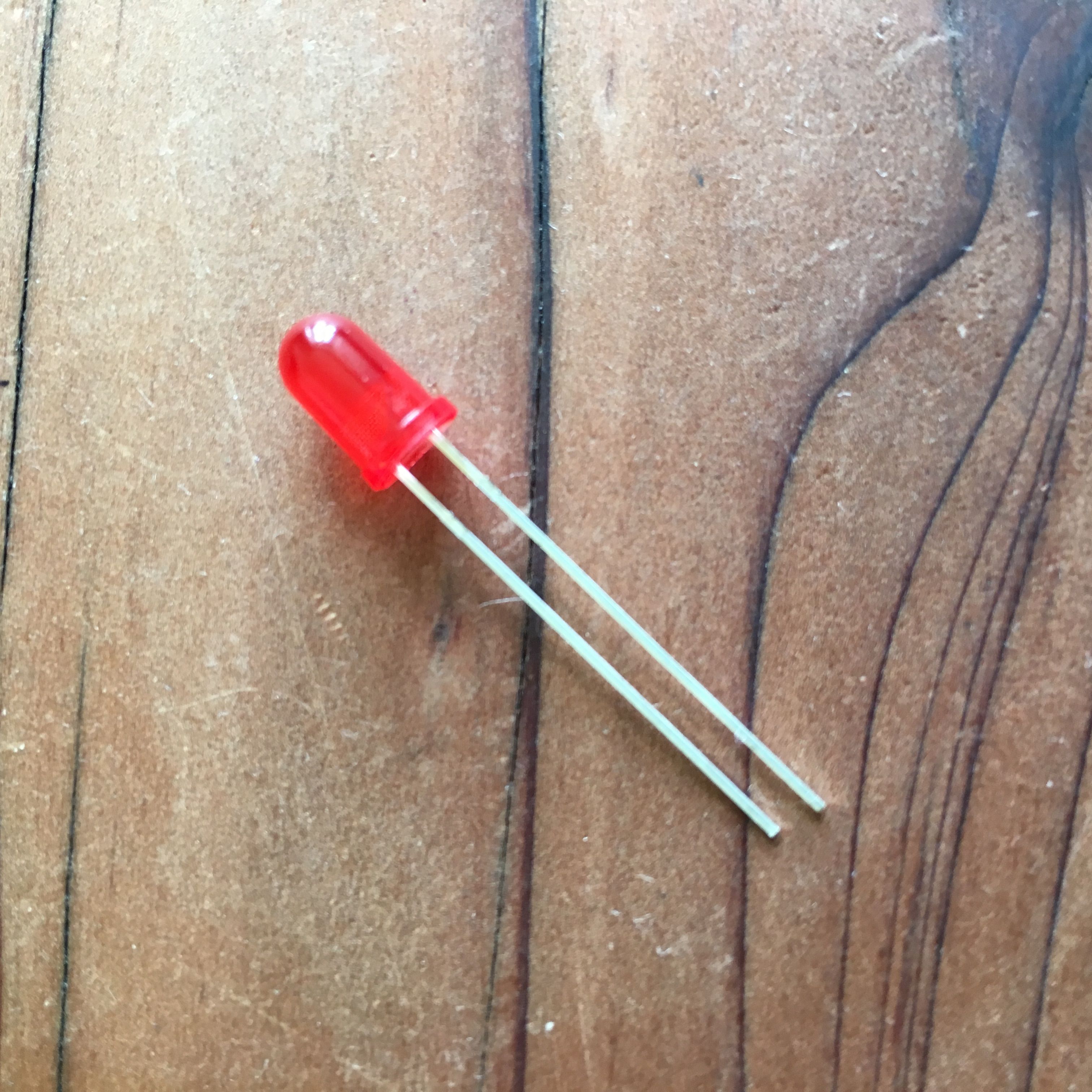
See the longer pin / leg sticking out of the red part? That's the anode terminal. The anode is the positive end of the LED. The shorter leg is the cathode - the negative side. Electrons will flow from the anode to the cathode when connected. You'll want to connect the positive end to something providing voltage, and the negative end needs to be connected to ground. All diodes are polarized, meaning they have these distinct positive and negative sides. And LEDs (light emitting diodes) happen to provide illumination when they're connected to an active circuit.
And they can be lots of pretty colors, too.
Okay, so here's our legally-required sketch for blinking an LED connected to digital pin 13 every half-second.
const int LED = 13;

void setup() {
    pinMode(LED, OUTPUT);
}

void loop() {
    digitalWrite(LED, HIGH);
    delay(500);
    digitalWrite(LED, LOW);
    delay(500);
}
Pretty simple, right? We first declare a constant variable for the pin we're using. The setup() function will run once per program, right before the loop() kicks off its infinite loop, so we'll just let the Arduino know that we want to set pin 13 to OUTPUT mode. And then during our infinite loop, we'll toggle the voltage to the pin by passing HIGH (5 volts) or LOW (0 volts) to our pin 13 using the digitalWrite function, pausing 500 milliseconds between these operations.
If you're coming from the Processing world, then this program structure of setup() and loop() should look very familiar, since it's literally the same.
The Arduino IDE provides an easy way to verify your programs compile before flashing them over to your actual Arduino, so I suggest clicking the Verify button first. This will catch syntax errors, like pesky missing semi-colons.
Next, we can set up our physical device.
I'm going to stick the LED into the Arduino, with the anode leg going into pin 13 and the cathode leg into ground. Note here that pin 13 is a special pin on the Arduino that has a resister built-in. If you try this with any other pin the Arduino, then the LED will burn out.
Finally, we can send our program from our computer to the Arduino over a USB connection by clicking the Upload button in the IDE. Your Arduino should flash happily once its complete, and then it's off to the infinite races.
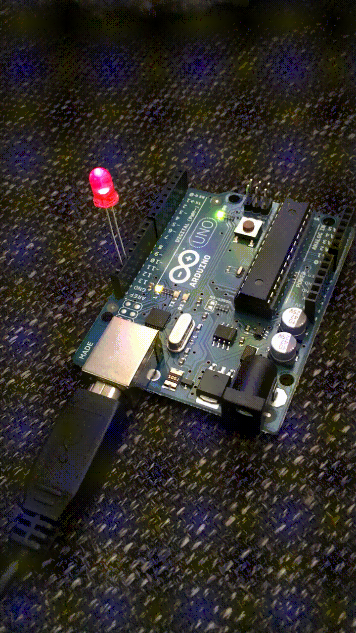
Look at that blinker. Pretty great, huh? Note that this gif definitely speeds things up a bit.
Putting the "S" in USB
So, as I continued building stuff, I inevitably found myself wanting to console.log the heck out of a program that wasn't working.
Let's talk about printing stuff with Arduino.
Your Arduino is connected to your computer via a USB cable. USB. USB. That has to stand for something, right? It does. It stands for "Universal Serial Bus." USB is a quote "industry standard" for communications between computers and peripherals. If you think back really hard to the time of Captain Marvel or even earlier, you might remember other ways that we connected peripherals to our computers -- like an dot matrix printer's parallel port or a PS/2 keyboard port. Well, in the time since Carol Danvers left us here to fend for ourselves, USB has taken over our hearts, minds, and wallets. But we're still using a "serial connection" when we're using USB devices - so we'll need to use the serial protocol to communicate with our Arduino.
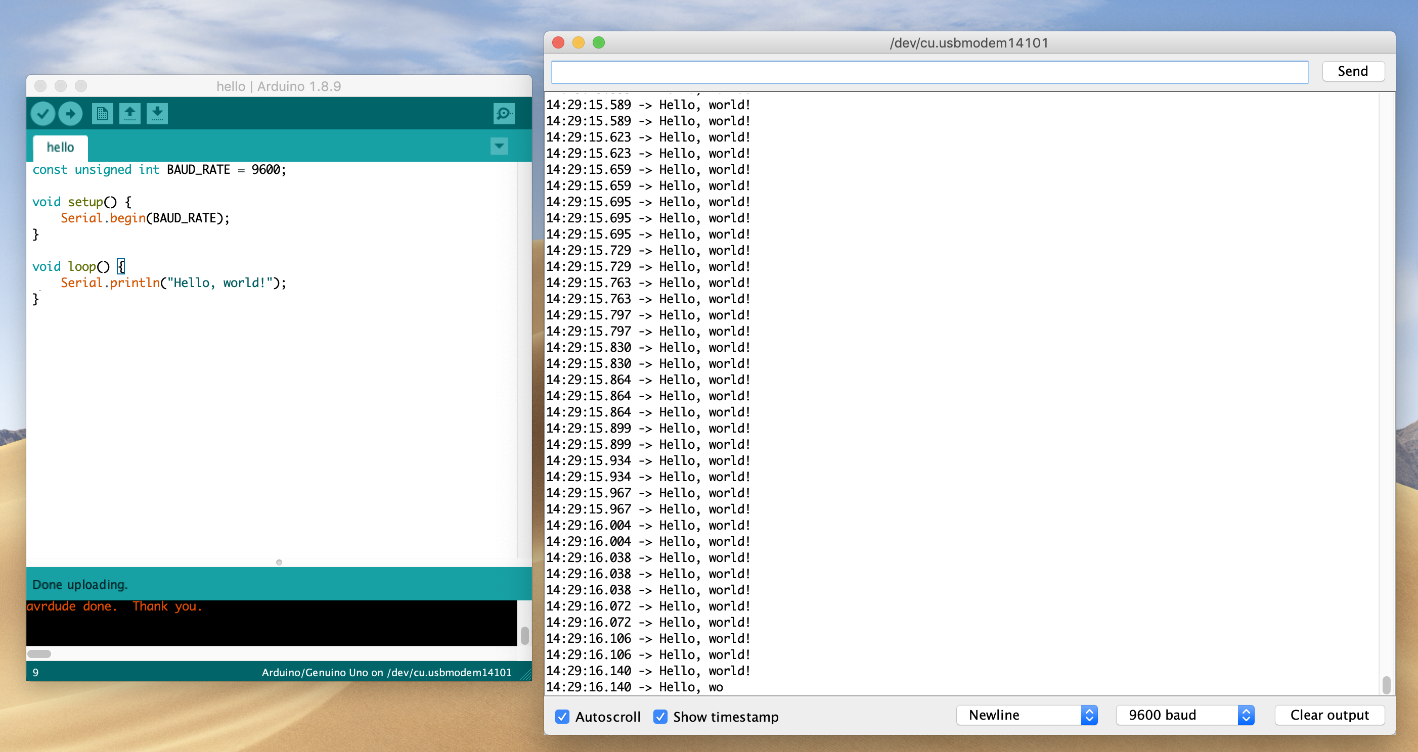
In other words, if we want to send or receive info from our Arduino program, we need to establish a serial connection with the device. Here's how you do that in a Processing sketch:
const unsigned int BAUD_RATE = 9600;

void setup() {
    Serial.begin(BAUD_RATE);
}

void loop() {
    Serial.println("Hello, world!");
}
Baud rate, huh? I know this baud term, too. Modems had baud rates, IIRC. Some Wikipedia-ing and Google-ing reveal that baud rates are the rates at which information is transferred in a serial channel. In this case, with a baud rate of 9600, we're transferring a max of 9600 bits per second. 9600 happens to be the standard baud rate for Arduinos, but I believe you can choose a different rate.
To view your "console", you can click the "Serial Monitor" button in the IDE.
In addition to viewing received information, you can also send messages back to the Arduino in this monitor using the text input on the top panel and the Send button. For example, you might write a program that toggled an LED on or off based on a specific input key.
What if you don't want to use the Serial Monitor in the Arduino IDE? Maybe it's time to let the old ways die. I agree. If you're on a Mac, then you can try running the screen command from your terminal, specifying both the name of your serial connection to your Arduino and the baud rate.
screen <name_of_serial_connection> 9600
In my case, the name of the connection was /dev/cu.usbmodem14101, which you can find in the Tools/Port menu of the Arduino IDE.
Word of warning, however. If you close this terminal window, it won't close the sesssion, and you'll be unable to Upload new programs to your Arduino. This is called a "detached screen" and it's annoying. You need to quit the screen somehow, and you can use this command to do so:
screen -X -S <name_of_session> quit
Oh, to get the name of the detached session, you can type:
screen -ls .
This whole serial communications thing opens up some interesting ideas, since you can have two way comms between your Arduino and something else. Forget Alexa. Not-okay, Google. Go away, Siri. Now you can build your own talking robotic best friend, instead. Hopefully gets some gears turning for you, too.
Counting in binary with LEDs
In general, life-goal-wise, I've been trying to get better at thinking and counting in binary, so I decided to build a little binary counter for my next Arduino project.
const unsigned int LED_BIT0 = 12;
const unsigned int LED_BIT1 = 11;
const unsigned int LED_BIT2 = 10;
const unsigned int LED_BIT3 = 9;

long result = 0;

void setup() {
  pinMode(LED_BIT0, OUTPUT);
  pinMode(LED_BIT1, OUTPUT);
  pinMode(LED_BIT2, OUTPUT);
  pinMode(LED_BIT3, OUTPUT);
}

void loop() {
  result++;
  if (result == 16) {
    result = 0;
  }
  output_result(result);
  delay(500);
}

void output_result(const long result) {
  digitalWrite(LED_BIT0, result & B0001);
  digitalWrite(LED_BIT1, result & B0010);
  digitalWrite(LED_BIT2, result & B0100);
  digitalWrite(LED_BIT3, result & B1000);
}
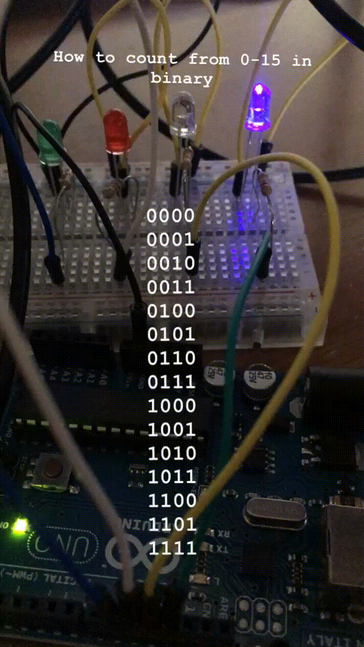
I'm not sure why the red LED isn't as bright as the other three LEDs. I tried swapping it out with another LED to no avail. But, hey, other than that, this thing works!
I also learned that breadboards are great. Being able to run all the cathode sides of the LEDs to the bottom negative row of the breadboard, and then only connecting that row once to the Arduino's ground port is pretty darn helpful. I have more to learn and appreciate here, for sure.
Also, this is the first time that I've really leveraged the power of the bitwise-and operator. I'm taking my result and bitwise-and it with a binary number that represents a binary digit (1's, 2's, 4's, 8's) for each of the LEDs. The bitwise-and operation returns true if result and our binary number both contain a 1 for the given binary digit. For example, let's look at the number 3
3 & B0001; // true
3 & B0010; // true
3 & B0100; // false
3 & B1000; // false
The final trick here is that digitalWrite function transforms true boolean values into HIGH (turn on the LED) and false into LOW (turn off the LED). So, for the number 3 the LED for the 1's digit and the 2's digit should be lit, and the 4's and 8's should be off.
That's pretty awesome and makes this code very concise. There's much more to explore here for me.
More tinkering
So, after a mere afternoon, I've learned a ton and had quite a bit of fun along the way.
What's next, you ask? Well, resistors are still perplexing. I'm not sure yet how to determine what level of resistence is needed for a given situation. I've already fried an LED (a delightful puff of smoke wisps out during its last gasp of life), likely for this very reason. It's also really hard to read those colorful bands to try to determine their resistance level. This seems like it could be a great little computer vision / deep learning app. Or perhaps I should just use my multimeter more regularly.
I'm also thinking more about the difference between analog and digital signals. Digital is binary (either on or off), whereas analog is continuous. Most of what we observe in life is an analog signal. So when we choose to digitize them, we need to choose specific moments to "sample" the values of the continuous signal. The Schmidt book explained that an audio CD takes a sample every 44,100 per second (or 44.1 kHz). Maybe this is why vinyl is back.
I thinking that my obvious next project here with Arduino is to make an alarm clock with binary numbers. There are tons of neat examples of this project across the web, and I think it could be a good way to learn / improve my soldering skills, as well as my quick mental binary counting, especially while groggy in the middle of the night.